In the previous blog post we went through our attempts at making molds to prototype the carbon fiber Radium board by utilizing FDM 3D printing, and the issues we came across with that technique.
During that process we decided it would be best to commit to making proper tooling with our Tormach 1100M CNC milling machine, even though each mold would have to be broken up into 4 individual pieces to fit in the machine, with 4 molds (16 pieces) in total.
This changed our approach to making the plug/pattern for the enclosure of the board. Due to the inaccuracy and slowness of 3D printing for large objects we initially tried to make a replica plug of the enclosure, adding a flange afterwards from which the top and bottom half of a two piece mold would be formed. The idea behind this was that after laying up the first half of the mold onto a plastic flange around the part, the flange could be pulled off and the second half of the mold could be laid up directly onto the first half to ensure both sides meet up in the middle perfectly with no gaps. But despite our efforts this method didn’t go well, so this time we took advantage of the accuracy of CNC machining and made two completely separate plugs with a flange already built into both sides – one plug for each half of the two piece mold that would form the enclosure of the board.
The deck had some major design updates as well. We went through many ideas for how to make the decks, from single sided parts with foam cores, to honeycomb cores sandwiched between two layers of carbon. The issue we were having is that carbon fiber parts usually have an accurate cosmetic side that is produced by the mold, and a rough uneven surface on the back from vacuum bagging, but we needed both sides of our deck to have an accurate surface.
We are stoked with the design we landed on in the end – two separate pieces of carbon fiber, with the underside piece including wavy patterns to add stiffness. These two parts are then glued back to back, so both outer surfaces are accurate and smooth. A urethane bumper gets glued in around the perimeter, so the deck is thick but hollow which not only makes it comfortable to hold but significantly reduces weight, enabling the finished deck to weigh just 1kg.
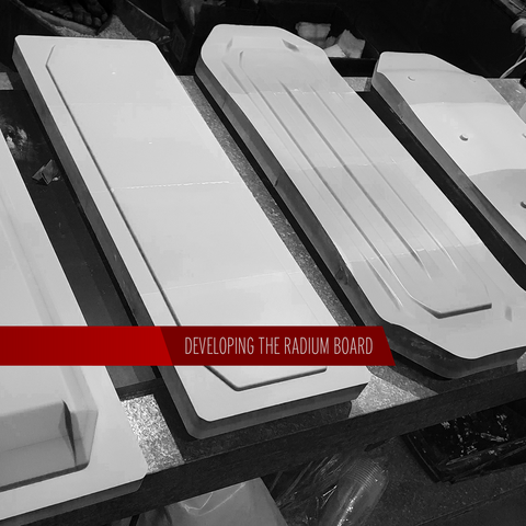
To machine the molds we needed a base material to mill down into the final shape, which had to be sturdy and easy to sand smooth and seal, as achieving a totally smooth surface with a milling machine is just not practical. We decided to use epoxy tooling board, because even though it was significantly more expensive than MDF, it’s a much better material for making molds as it can retain fine details and is very rigid and stable, whereas MDF has a tendency to warp with moisture and internal stresses. However we did use MDF to make the mold for the urethane bumper as it was a simple 2D shape with no need for accuracy.

One of the most difficult parts of CNC milling is holding the parts, and we benefited greatly from the tooling boards strength here, by drilling 3 holes and tapping threads into the tooling board itself we were able to just bolt the blanks to a block of aluminum that we’d clamp in the vise, allowing all edges to be machined away without the cutter colliding with a clamp.
The molds had to be split into sections in CAD, and using the same software (Fusion 360) we created the tool paths to tell the machine how to go about removing the material, including deciding how rough of a finish to leave. The smoother the surface, the longer it takes to machine and it gets to a point where super smooth takes so many hours to machine that its faster to sand it by hand, so we landed on a finish that took around 2 hours of machining for each of the 16 section.


We used 3 tools – two different sized ball end mills for finishing, and a high speed steel 2 flute square end mill to rough out most of the material, which we experienced problems with. The tooling board basically turns to dust as its machined away, and we think the dust created a lot of friction and abrasion, causing the high speed steel cutter to heat up and go blunt after just a few hours of machining. The effect of this was that the pressure from the dull cutter caused the tooling board to not just machine away nicely, but instead it would break off in chunks, causing more material to be removed than was intended.


So to address this we used a constant air blast on the cutter to remove excess dust (causing it to end up on absolutely everything in the workshop) in order to keep the cutter cool and minimize re-cutting of abrasive particles which greatly extended tool lifespan. We also optimized the tool paths to only cut in certain ways as to not create thin sections that chip away.

After rough shaping with the 2 flute square end mill, a 12.7mm ball end mill is used to achieve the final shape and surface finish.

A small 3.17mm ball end mill then reaches into the tighter corners to remove the last bits of material that the 12.7mm couldn’t reach.


After this I vowed never to machine tooling board again, as not only were the entire contents of the workshop covered in fine dust, but the Tormach was so caked up with tooling board that it took 2 days to fully clean.

But it got the job done, and after a week of late nights we had all the individual pieces ready to be glued together forming the final molds.


There were still some chunks taken out on some of the parts before we got on top of that issue, and we just filled those gaps with bog.

After correcting any defects we sanded the surface smooth by hand, working our way up from 400 grit to 1200, and then applied a cut and polish.

After this we had a very smooth surface but still technically a porous one, meaning that resin can soak into the tooling board and bond to it. So to address this we used a product called TR Sealer Glaze, applying 2 coats and buffing them back to ensure the surface couldn’t absorb any resin under vacuum.

But epoxy is sticky stuff and sealing the surface alone won’t stop it from adhering, so we also applied 6 coats of honey wax mold release agent, placing the molds into our homemade curing oven to dry the wax faster before we had to buff it back between each coat. This still takes a while when you have to do 6 coats across 4 different molds.
At this stage we had two molds for the two piece deck ready to go, as they are already negative molds that we can lay the carbon straight into. However the enclosure molds were still technically a positive/plug that we needed to form the two piece fiberglass mold that we would use to lay up our carbon fiber enclosure, so we will go through that in the next part of Developing the Radium board.